help with series/parallel phase in/out wiring for JM
-
theswiftbrownfox

- PAT PEND

- Posts: 6
- Joined: Fri Jan 30, 2015 9:15 am
help with series/parallel phase in/out wiring for JM
I'm having trouble finding an applicable wiring diagram to help me wire a series/parallel switch and a phase switch to my stock j mascis jazz master. I'd like to keep the rhythm circuit as is, add two slider switches on the treble side and, replace the three way toggle with either a three way slider or individual on/off sliders for a pseudo jaguar look. I haven't done much guitar wiring but i do have some soldering experience, and I'm confident i can follow a diagram, i just can't find the right diagram and am unsure about making my own from looking at others with similar components. A point in the right direction or any help at all would be greatly appreciated. just to be clear I'm trying to wire it so that i have all combinations of series/parallel and in and out of phase for two pickups while keeping the rhythm circuit as is. thank you for your help in advance.
-
hpr_hpr

- PAT. # 2.972.923

- Posts: 434
- Joined: Fri Apr 03, 2015 9:48 am
Re: help with series/parallel phase in/out wiring for JM
Replays the treble side switching
Wire the bridge pickup into a 2 position dpdt set up for switching the phase (don't worry about 'polarity' here it's all good)
 .
.
Take the outputs from the phase switch and from the other pickup into a series/parralel/neck/bride switch
(these are 2 2 position spdt switches) don't worry about the 'polarity' out of out of the phase switch ... all ways work .. hot now goes to master tone / master volume as before ....
Wire the bridge pickup into a 2 position dpdt set up for switching the phase (don't worry about 'polarity' here it's all good)
. Take the outputs from the phase switch and from the other pickup into a series/parralel/neck/bride switch
(these are 2 2 position spdt switches) don't worry about the 'polarity' out of out of the phase switch ... all ways work .. hot now goes to master tone / master volume as before ....
Last edited by hpr_hpr on Sun Sep 06, 2015 7:23 pm, edited 1 time in total.
When thinking about any advice given always ask yourself "why would (s)he know more than I do".
-
theswiftbrownfox
- PAT PEND
- Posts: 6
- Joined: Fri Jan 30, 2015 9:15 am
Re: help with series/parallel phase in/out wiring for JM
thank you so much! I really do appreciate the help. just so I'm sure i understand, if i wire the bridge pickup to the phase switch like in your first picture, the output of the phase switch would be wired in place of "bridge" in the second picture. correct? and all of this would be after the pickup selector switchs but before the tone and volume right? . sorry if these are stupid questions, it's late and i only ever get more confused at this hour.
-
hpr_hpr
- PAT. # 2.972.923
- Posts: 434
- Joined: Fri Apr 03, 2015 9:48 am
Re: help with series/parallel phase in/out wiring for JM
Yep on the placement of the phase switch
I don't know the exact default wirering of the jmjm .... I'm assuming the pups are wired to ground ... the bridge is wired to the selector switch and that output goes to the volume/tone switches of the treble side .... the neck is wired to both the rytm tone controls and the selector switch .... The output from both sets of volume/tone controls goes to the rythm/lead selector switch which in turn is connected to the output Jack ..... don't know if all that is true but it would be how I would wire it up without prior knowledge ...
So disconnect the bridge from ground and pu selector switch and wire to the phase switch, disconnect the neck from the pu selector switch (leave it conneccted to ground, no need to change that and wire it into the 2 spdt switches (put in the jumper between the switches first - easier than doing it later) followed by connecting the phase switch to the same ..... so neck pu ground is NOT connected to the spdt switch, Do connect this pole to GND though ... wire the output to the rhythm/lead selector switch and you are done ... well except for mounting the switches of course .....
When thinking about any advice given always ask yourself "why would (s)he know more than I do".
-
hpr_hpr
- PAT. # 2.972.923
- Posts: 434
- Joined: Fri Apr 03, 2015 9:48 am
Re: help with series/parallel phase in/out wiring for JM
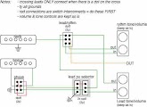
Here is a complete diagram . . . .
When thinking about any advice given always ask yourself "why would (s)he know more than I do".
-
theswiftbrownfox
- PAT PEND
- Posts: 6
- Joined: Fri Jan 30, 2015 9:15 am
Re: help with series/parallel phase in/out wiring for JM
i think i mostly follow your previous post, which seems to make sense. I really appreciate the full diagram and thats really exactly what i need but i can't see anything on it, the image is too small. It's only 165 x 120 pixels and everything comes out all grainy with zoom. Am i viewing it incorrectly? if you have a larger version i'd love to see that, this seems like it would be perfect.
-
hpr_hpr
- PAT. # 2.972.923
- Posts: 434
- Joined: Fri Apr 03, 2015 9:48 am
Re: help with series/parallel phase in/out wiring for JM
Sorry about that, no idea why THAT happened the original file is substancially larger than 120x165 pixels .... PDF for download here https://www.dropbox.com/s/vpdl7z0z1vb2r3s/JMJM_RW.pdf
Oh and I found one oops in the diagram ... the bottom left pin on the phase switch should NOT be connected to ground ... sorry copied from another diagram and forgot to delete it .... with that ground there you won't ever get the pups in series .... in fact I think the series setting results in 'no sound'.
Oh and I found one oops in the diagram ... the bottom left pin on the phase switch should NOT be connected to ground ... sorry copied from another diagram and forgot to delete it .... with that ground there you won't ever get the pups in series .... in fact I think the series setting results in 'no sound'.
When thinking about any advice given always ask yourself "why would (s)he know more than I do".
-
theswiftbrownfox
- PAT PEND
- Posts: 6
- Joined: Fri Jan 30, 2015 9:15 am
Re: help with series/parallel phase in/out wiring for JM
thank you so much for the diagram, that helps to make things much more clear, i had started trying to draw my own up of how i thought it should look and... well lets just say i'm glad to have this one. one last question. you said that that connection on the phase switch shouldn't go to ground, should it be going to the series switch? I'm just a little confused because you mention series/parallel in your comment but i don't see a series/parallel switch in the diagram, am i meant to add the series switch from your earlier post into this diagram? if so I'm a little confused as to where it goes. sorry for all the follow up questions, I'm just excited to get all the switches I'll need and start wiring it up!
-
theswiftbrownfox
- PAT PEND
- Posts: 6
- Joined: Fri Jan 30, 2015 9:15 am
Re: help with series/parallel phase in/out wiring for JM
oh i get it now!  i guess originally i hadn't understood that the series switch was incorporated into the pickup selectors. still a little confused about what the pickup selection will be like though, but I'm sure i can figure that out after wiring. i originally thought id end up with four switches, an on/off for each pickup and one for series parallel and one for phase reverse. i guess its better to get it done with three though right? I'd like to add a third pickup to this guitar some time soon and then ill put individual on/off for each pup, along with two or three more for phase and series switching (i dig the too many switches look). anyways thanks again for all your help! and sorry if i haven't been the sharpest student.
-
hpr_hpr
- PAT. # 2.972.923
- Posts: 434
- Joined: Fri Apr 03, 2015 9:48 am
Re: help with series/parallel phase in/out wiring for JM
You CAN do it that way (have individual switches for each pickup) BUT there will be at least one switch configuration in which there will be NO sound (both pickups off) in that case. This way there are NO 'dead spots' on the switches . . . also (given that you now need 3 sliders instead of a single toggle) you can use a a 3 switch jag control plate to mount them so you can 'repurpose' you original pick guard if you want to . . . the way you are suggesting take 4 switches like you said . . . phase, series/parallel, on/off neck, on/off bridge . . . but you get the same results.
lead PU selector:
both down (connections from center to top) : series
both up (connections from center to bottom): parallel
left up / right down : neck (no connection to ground on bridge PU)
left down / right up : bridge (no connection to OUT on neck PU)
You CAN substitute a DPDT switch for the right switch in the lead PU selector and disconnect the bridge PU from OUT when selecting only the neck PU . . . electrically this is 'cleaner' but I doubt if you'll be able to hear the difference.
When thinking about any advice given always ask yourself "why would (s)he know more than I do".