Yo Amon! That shouldn't be that difficult to do! I might have some time between now and Sunday. Let me see what I can cook up for you.
For the coil split, you want the screw coil (inner or outer?) to be on or off for the split single-coil mode?
Shadoweclipse13's Master Schematic Page!
-
Shadoweclipse13

- PAT. # 2.972.923

- Posts: 12448
- Joined: Fri Feb 07, 2014 9:22 pm
- Location: Stuck in the dimension of imagination
Re: Shadoweclipse13's Master Schematic Page!
Pickup Switching Mad Scientist
http://www.offsetguitars.com/forums/viewtopic.php?f=8&t=104282&p=1438384#p1438384
http://www.offsetguitars.com/forums/viewtopic.php?f=8&t=104282&p=1438384#p1438384
-
Amon 7.L

- PAT. # 2.972.923
- Posts: 743
- Joined: Sun Aug 28, 2011 5:45 am
Re: Shadoweclipse13's Master Schematic Page!
Jason! My man! Hi!Shadoweclipse13 wrote: ↑Thu Mar 26, 2020 1:54 amYo Amon! That shouldn't be that difficult to do! I might have some time between now and Sunday. Let me see what I can cook up for you.
For the coil split, you want the screw coil (inner or outer?) to be on or off for the split single-coil mode?
Thank you, just take it easy I won't be going anywhere
Re the coil split, in split-coil mode I'd like to have the screw side closer to the bridge being the one active.
-
Debaser

- PAT. # 2.972.923
- Posts: 417
- Joined: Mon Apr 21, 2014 2:12 pm
- Location: Phoenix AZ
Re: Shadoweclipse13's Master Schematic Page!
I didn’t have time to look at every page, so if this has been covered pay no mind.
I installed this switch wiring on a Squier VM Mustang, the later ones with an extra wide switch cavity. Vintage, reissue, etc will need to be widened to accept the 3P3T slide switch. I still would make this happen on another Mustang, I like it that much. All original Mustang options are available, but includes the very appealing series position, which is a ‘blower’ type situation that kills all other selected positions.

I installed this switch wiring on a Squier VM Mustang, the later ones with an extra wide switch cavity. Vintage, reissue, etc will need to be widened to accept the 3P3T slide switch. I still would make this happen on another Mustang, I like it that much. All original Mustang options are available, but includes the very appealing series position, which is a ‘blower’ type situation that kills all other selected positions.
50,000 watts out of Mexico, this is the BorderRadio...
-
JVG
- PAT. # 2.972.923
- Posts: 1413
- Joined: Thu Aug 06, 2015 9:54 pm
- Location: Sydney, Straya
Re: Shadoweclipse13's Master Schematic Page!
Hey Shadow,
Hopefully a simple request. I’m thinking of doing the Mustang series-parallel mod, but would like the 2nd switch to have a “kill” position, i.e. parallel-kill-series. The 1st switch would be the pickup selector. Possible?
Cheers!
J.
Hopefully a simple request. I’m thinking of doing the Mustang series-parallel mod, but would like the 2nd switch to have a “kill” position, i.e. parallel-kill-series. The 1st switch would be the pickup selector. Possible?
Cheers!
J.
-
Futuron

- PAT. # 2.972.923
- Posts: 1234
- Joined: Fri Nov 10, 2017 3:19 am
- Location: Australia

-
JVG
- PAT. # 2.972.923
- Posts: 1413
- Joined: Thu Aug 06, 2015 9:54 pm
- Location: Sydney, Straya
Re: Shadoweclipse13's Master Schematic Page!
Thanks Futuron!
I was wondering about this, but tied myself in a knot. Why doesn’t the yellow wire (in your diagram) feed the neck pickup signal through to the other switch regardless of whether it’s in position 4, 5, or 6?
Every time i think i understand guitar electronics, i realise that i actually don’t!
J.
I was wondering about this, but tied myself in a knot. Why doesn’t the yellow wire (in your diagram) feed the neck pickup signal through to the other switch regardless of whether it’s in position 4, 5, or 6?
Every time i think i understand guitar electronics, i realise that i actually don’t!
J.
-
Futuron
- PAT. # 2.972.923
- Posts: 1234
- Joined: Fri Nov 10, 2017 3:19 am
- Location: Australia
Re: Shadoweclipse13's Master Schematic Page!
Sure, the neck 'hot' wire is always connected to the other switch, but the 'ground' wire is not always going to ground. Unlike the bridge pickup in this instance, where the 'ground' is always connected but the 'hot' isn't.JVG wrote: ↑Tue Apr 14, 2020 2:18 amThanks Futuron!
I was wondering about this, but tied myself in a knot. Why doesn’t the yellow wire (in your diagram) feed the neck pickup signal through to the other switch regardless of whether it’s in position 4, 5, or 6?
Every time i think i understand guitar electronics, i realise that i actually don’t!
J.
To get a pickup output, both 'hot' and 'ground' must be on either side of the circuit. Cut one off (open circuit) or tie them together (short circuit) and the pickup won't be output.
So by tracing the black neck 'ground' wire, you can see that in position 4 it is connected directly to ground, in position 5 it's not connected to anything, and in position 6 it's connected to bridge 'hot' and through that pickup to ground.
-
Debaser
- PAT. # 2.972.923
- Posts: 417
- Joined: Mon Apr 21, 2014 2:12 pm
- Location: Phoenix AZ
Re: Shadoweclipse13's Master Schematic Page!
Ms paint, so good 
50,000 watts out of Mexico, this is the BorderRadio...
-
JVG
- PAT. # 2.972.923
- Posts: 1413
- Joined: Thu Aug 06, 2015 9:54 pm
- Location: Sydney, Straya
Re: Shadoweclipse13's Master Schematic Page!
Futuron wrote: ↑Tue Apr 14, 2020 8:27 pmSure, the neck 'hot' wire is always connected to the other switch, but the 'ground' wire is not always going to ground. Unlike the bridge pickup in this instance, where the 'ground' is always connected but the 'hot' isn't.JVG wrote: ↑Tue Apr 14, 2020 2:18 amThanks Futuron!
I was wondering about this, but tied myself in a knot. Why doesn’t the yellow wire (in your diagram) feed the neck pickup signal through to the other switch regardless of whether it’s in position 4, 5, or 6?
Every time i think i understand guitar electronics, i realise that i actually don’t!
J.
To get a pickup output, both 'hot' and 'ground' must be on either side of the circuit. Cut one off (open circuit) or tie them together (short circuit) and the pickup won't be output.
So by tracing the black neck 'ground' wire, you can see that in position 4 it is connected directly to ground, in position 5 it's not connected to anything, and in position 6 it's connected to bridge 'hot' and through that pickup to ground.
Great explanation. I get it. Thanks again!
-
Marshsticks

- PAT PEND

- Posts: 8
- Joined: Wed Apr 15, 2020 2:11 am
Re: Shadoweclipse13's Master Schematic Page!
Hey, this appears to be the right place for this... 
I was hoping to get some help with the specific wiring for my Jazzmasters! So at present I have the lead circuit as stock (master tone/ vol, 3 way switch) and I've done the series/ parallel mod to the rhythm switch, with up being series and the two roller pots being removed entirely.
What I'd like to do is expand on this to use the holes and make the guitar a little more flexible to my needs. I've heard people mention a series only bright switch such as in the Johhny Marr Jag, I'd like to wire one of those in where the rhythm cicuit volume was. I'd also like to repurpose the 1meg mini roller pot as an independent tone control for the neck pickup, putting that in the lower rhythm cicuit hole. Meaning I'd then have... master volume, lower tone as bridge only, roller pot as tone for neck only, series parallel switch on the upper horn and a series only bright switch next to it. Bonus points if you can make the 'kill' position bridge in series rather than neck in series which it currently is, as I'm far more likely to want to step down from series to neck only for rhythm playing.
Can you help me out with the wiring for this? I can follow a schematic fine but the actual wiring, particularly the bright switch, is completely over my head! Thanks in advance!
-
timtam

- PAT. # 2.972.923
- Posts: 2746
- Joined: Sun Oct 22, 2017 2:42 am
- Location: Melbourne
Re: Shadoweclipse13's Master Schematic Page!
The series bright switch in the Marr circuit is dead simple - just a 0.003uF cap DPDT switch circuit in between the negative end of the neck pickup and the positive of the bridge pickup, when the series circuit that connects the pickup ends in that way is selected (on the 4way in the Marr), as in the schematic ...Marshsticks wrote: ↑Thu Apr 16, 2020 2:08 amHey, this appears to be the right place for this...
I was hoping to get some help with the specific wiring for my Jazzmasters! So at present I have the lead circuit as stock (master tone/ vol, 3 way switch) and I've done the series/ parallel mod to the rhythm switch, with up being series and the two roller pots being removed entirely.
What I'd like to do is expand on this to use the holes and make the guitar a little more flexible to my needs. I've heard people mention a series only bright switch such as in the Johhny Marr Jag, I'd like to wire one of those in where the rhythm cicuit volume was. I'd also like to repurpose the 1meg mini roller pot as an independent tone control for the neck pickup, putting that in the lower rhythm cicuit hole. Meaning I'd then have... master volume, lower tone as bridge only, roller pot as tone for neck only, series parallel switch on the upper horn and a series only bright switch next to it. Bonus points if you can make the 'kill' position bridge in series rather than neck in series which it currently is, as I'm far more likely to want to step down from series to neck only for rhythm playing.
Can you help me out with the wiring for this? I can follow a schematic fine but the actual wiring, particularly the bright switch, is completely over my head! Thanks in advance!

Marr wiring diagram ...
https://www.fmicassets.com/Damroot/Orig ... B_SISD.pdf
"I just knew I wanted to make a sound that was the complete opposite of a Les Paul, and that’s pretty much a Jaguar." Rowland S. Howard.
-
Amon 7.L
- PAT. # 2.972.923
- Posts: 743
- Joined: Sun Aug 28, 2011 5:45 am
Re: Shadoweclipse13's Master Schematic Page!
lil bump.Amon 7.L wrote: ↑Tue Mar 24, 2020 6:15 amCalling the masters of schematics for a little help with this wiring.
I'm planning to swap the humbucker of my silverburst Jaguar with either a DiMarzio SuperDistortion I have lying around or a cheap Belcat JB lookalike I'm planning to test.
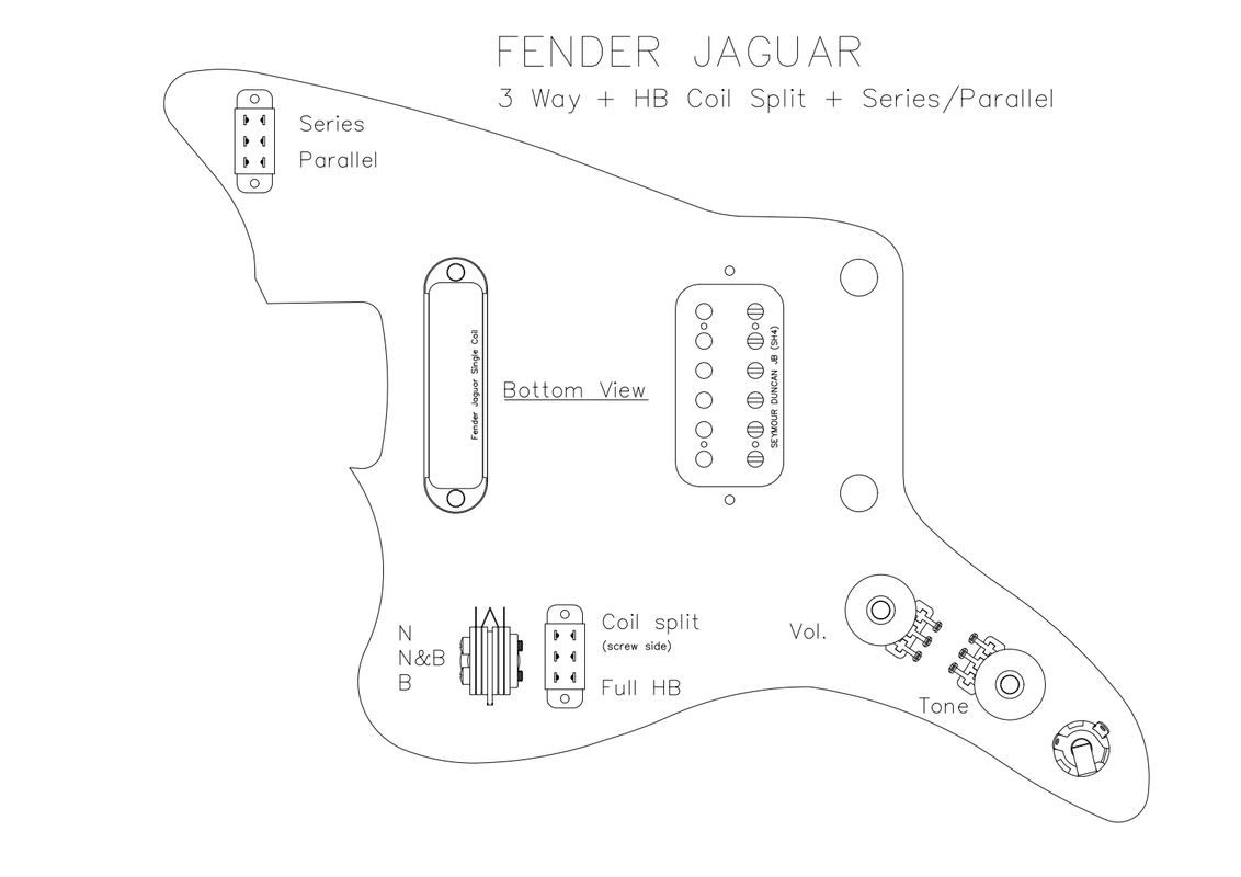
Thing is, the strangle switch is not of any use for me, so I'd like to have it wired so that it splits the hb and have the screw-side of the coil usable. Also, I'd like to have the option of having the series/parallel in the upper rhythm switch, like so:
I thank in advance anyone who will help out
Can anyone help me out with this schematic?
-
timtam
- PAT. # 2.972.923
- Posts: 2746
- Joined: Sun Oct 22, 2017 2:42 am
- Location: Melbourne
Re: Shadoweclipse13's Master Schematic Page!
I'll handle the coil split off the existing strangle DPDT switch.Amon 7.L wrote: ↑Thu Apr 16, 2020 5:04 amlil bump.Amon 7.L wrote: ↑Tue Mar 24, 2020 6:15 amCalling the masters of schematics for a little help with this wiring.
I'm planning to swap the humbucker of my silverburst Jaguar with either a DiMarzio SuperDistortion I have lying around or a cheap Belcat JB lookalike I'm planning to test.
Thing is, the strangle switch is not of any use for me, so I'd like to have it wired so that it splits the hb and have the screw-side of the coil usable. Also, I'd like to have the option of having the series/parallel in the upper rhythm switch, like so:
I thank in advance anyone who will help out
Can anyone help me out with this schematic?
To bridge the circuit where the strangle was, just unsolder the input and output wires from the switch (and the cap) and solder them together instead (cover with heatshrink) - see stock jag wiring below.
Then add the coil split like this. Connect the bridge HB's screw side hot to the pickup selector switch. Connect the HB's 2 middle/coil-joining wires, and the ground side of the slug coil, to the old strangle DPDT as shown below. Also connect a ground wire there, as shown. So the switch will be connecting just the slug ground side to ground (normal full HB), or grounding the wires between the coils (thus selecting just the screw coil).
It's possible that this combination (full HB and/or split HB) with the SC could end up out of phase, in which case you'd have to make some further mods. Simplest would be to just flip the destination points where the hot and ground wires on the neck SC connect (after separating the SC coil ground wire from the claw and adding a separate claw ground wire).


"I just knew I wanted to make a sound that was the complete opposite of a Les Paul, and that’s pretty much a Jaguar." Rowland S. Howard.
-
Amon 7.L
- PAT. # 2.972.923
- Posts: 743
- Joined: Sun Aug 28, 2011 5:45 am
Re: Shadoweclipse13's Master Schematic Page!
timtam wrote: ↑Thu Apr 16, 2020 5:53 amI'll handle the coil split off the existing strangle DPDT switch.Amon 7.L wrote: ↑Thu Apr 16, 2020 5:04 amlil bump.Amon 7.L wrote: ↑Tue Mar 24, 2020 6:15 amCalling the masters of schematics for a little help with this wiring.
I'm planning to swap the humbucker of my silverburst Jaguar with either a DiMarzio SuperDistortion I have lying around or a cheap Belcat JB lookalike I'm planning to test.
Thing is, the strangle switch is not of any use for me, so I'd like to have it wired so that it splits the hb and have the screw-side of the coil usable. Also, I'd like to have the option of having the series/parallel in the upper rhythm switch, like so:
I thank in advance anyone who will help out
Can anyone help me out with this schematic?
To bridge the circuit where the strangle was, just unsolder the input and output wires from the switch (and the cap) and solder them together instead (cover with heatshrink) - see stock jag wiring below.
Then add the coil split like this. Connect the bridge HB's screw side hot to the pickup selector switch. Connect the HB's 2 middle/coil-joining wires, and the ground side of the slug coil, to the old strangle DPDT as shown below. Also connect a ground wire there, as shown. So the switch will be connecting just the slug ground side to ground (normal full HB), or grounding the wires between the coils (thus selecting just the screw coil).
It's possible that this combination (full HB and/or split HB) with the SC could end up out of phase, in which case you'd have to make some further mods. Simplest would be to just flip the destination points where the hot and ground wires on the neck SC connect (after separating the SC coil ground wire from the claw and adding a separate claw ground wire).
Thanks a lot for your input timtam, I really do.
Thing is, and I feel really dumb for it, I'm completely useless at decipher electronics wiring and drawn the new one accordingly, I tried to follow your description and the schematics you've posted but, for the life of me, I have no idea on how to translate it.
I can only solder according to a given diagram, nothing more. That's why I included a blank layout on which to drawn the connections between parts as per description.
I do apologies for my lack of expertise on the subject, that's why I've asked for a better help with the drawing.
-
Marshsticks
- PAT PEND
- Posts: 8
- Joined: Wed Apr 15, 2020 2:11 am
Re: Shadoweclipse13's Master Schematic Page!
Thanks, you're right that it does seem very simple! With the three way toggle and dedicated series/parallel set up, where exactly would I wire it?timtam wrote: ↑Thu Apr 16, 2020 2:58 amThe series bright switch in the Marr circuit is dead simple - just a 0.003uF cap DPDT switch circuit in between the negative end of the neck pickup and the positive of the bridge pickup, when the series circuit that connects the pickup ends in that way is selected (on the 4way in the Marr), as in the schematic ...Marshsticks wrote: ↑Thu Apr 16, 2020 2:08 amHey, this appears to be the right place for this...
I was hoping to get some help with the specific wiring for my Jazzmasters! So at present I have the lead circuit as stock (master tone/ vol, 3 way switch) and I've done the series/ parallel mod to the rhythm switch, with up being series and the two roller pots being removed entirely.
What I'd like to do is expand on this to use the holes and make the guitar a little more flexible to my needs. I've heard people mention a series only bright switch such as in the Johhny Marr Jag, I'd like to wire one of those in where the rhythm cicuit volume was. I'd also like to repurpose the 1meg mini roller pot as an independent tone control for the neck pickup, putting that in the lower rhythm cicuit hole. Meaning I'd then have... master volume, lower tone as bridge only, roller pot as tone for neck only, series parallel switch on the upper horn and a series only bright switch next to it. Bonus points if you can make the 'kill' position bridge in series rather than neck in series which it currently is, as I'm far more likely to want to step down from series to neck only for rhythm playing.
Can you help me out with the wiring for this? I can follow a schematic fine but the actual wiring, particularly the bright switch, is completely over my head! Thanks in advance!
Marr wiring diagram ...
https://www.fmicassets.com/Damroot/Orig ... B_SISD.pdf