Shadoweclipse13's Master Schematic Page!

Talk about modding or building your own guitar from scratch.
Post Reply
User avatar
bodhi
PAT. # 2.972.923
PAT. # 2.972.923
Posts: 462
Joined: Mon May 20, 2019 12:47 pm

Re: Shadoweclipse13's Master Schematic Page!

Post by bodhi » Tue Sep 01, 2020 1:14 pm

Nvmabee wrote:
Tue Jul 14, 2020 10:26 am
I'm back with this Cobain jag modification.

this is admittedly ambitious for one of my first custom wire jobs but it should/could in theory work.

I'm about ready to revert to a standard KC schematic - in general the idea work but nothing works perfectly:
• I think I have the unfortunate challenge of a ground loop AND missing grounds...
• stuff that should be working isn't - and the tricky business seems to actually work (partially)
• that 2-cap strangle switch makes me want to rip my hair out - the top position works, the bottom position works but the middle clean position is dead... how?
• the pickup selector detail is pulled directly from a mustang diagram... it should work perfectly but when I tap with a screw driver both pups give feedback in all 3 positions...
• the series/parallel/split switch seems to work on one, which is reassuring. if I can get one to work I'll match the other to it... just want to get some advice on how the switch is configured... does it actually work or am I hearing what I want to hear?
• I would be content reverting to two way switches (coil split), standard strangle, and a 3 way toggle at this point, but still need some advice using a 2 way (6 lug) jag switches to achieve this.

I know this is a bunch questions but they are ultimately a bunch of individual questions - feedback on any one of them or the digram itself would be helpful

FYI the four 3-way switches are mounted in a modified bass vi switch plate - which means the pickgaurd is modified and there is tons of extra routed room in the body cavity.

questions are in the image.

Image
Did this get fixed?

Might well be a little late, but I'd suggest you'd work through this in pieces. Can't see anything immediately wrong with the highlights in the wiring, but I'm a bit suspicious of the tone pot phase reversal...
Jazzmaster project (got a body, placeholder neck, some pickups and ideas)
Tokai Telecaster Thinline with Creamery Pickups Filtertron and Tapped Tele
Blake Mills-inspired Strat project w/ Gold Foil and slide pickup

User avatar
Pearlygates59
PAT PEND
PAT PEND
Posts: 3
Joined: Mon Aug 31, 2020 8:39 am

Re: Shadoweclipse13's Master Schematic Page!

Post by Pearlygates59 » Tue Sep 01, 2020 6:17 pm

bodhi wrote:
Tue Sep 01, 2020 1:07 pm
Pearlygates59 wrote:
Mon Aug 31, 2020 10:50 pm


Thanks! I've another guitar wired like the Red Special so that's fine!

Cheers

Hi all

Help required!

I'm hopeless at schematics and was wondering if anyone can help me out?

My project requirements are:

3x Humbuckers (4 wire)
3x individual on / off switches in series (like Brian May); I have 3x DPDT On/On switches for this
1x Volume / Push Pull for Neck Humbucker Phase Reversal
1x Tone Push / Pull for Bridge and Mid Pickup outer coil splits.

Can anyone help?!

Many thanks
You can base the thing on the Red Special wiring, just the neck phase reversal is on the volume pot, and leave the other phase toggles out: http://guitarwiring.blogspot.com/2011/0 ... -some.html

The dual coil split should work in such a way that whatever humbucker wiring you have, hook the left and the right side of the push-pull to one humbucker each like this:

Code: Select all

 [ "finish" of coil connected to middle lug, "start" of other coil ]
 [ ground and either coil "start" on humbucker                     ]
 [  <not connected>                                                ]
Each line is a lug. With that, when the push-pull is in the bottom ("normal position"), the humbucker is working normally, and when pulled up, one coil is canceled out.

The final wire from the humbucker is your hot lead, eg. red, grey and blue on the Red Special wiring image.

User avatar
Shadoweclipse13
PAT. # 2.972.923
PAT. # 2.972.923
Posts: 12446
Joined: Fri Feb 07, 2014 9:22 pm
Location: Stuck in the dimension of imagination

Re: Shadoweclipse13's Master Schematic Page!

Post by Shadoweclipse13 » Sun Sep 13, 2020 8:42 pm

Deep apology to anyone I said I'd work on a schematic for. I've been stupid busy, dealing with some shit at home and work, and have been stressed and generally unmotivated to do anything on my computer. I'm still gonna be taking a hiatus from doing schematics for a while, but I am going to try to get a couple schematics done for one or two people that I agreed to make one for before I announced a hiatus.

Also, had a neat idea I might try to figure out. Since the JM schematic where the rhythm circuit can affect both pickups is fairly popular, I had the idea that if 2 3PDT Mustang-style switches were used instead of a 3-way toggle, it might be possible to have a JM that has a 3-way switch for both rhythm AND lead circuits. That way, you could have a preset like the original rhythm circuit: if you wanted the neck pickup for rhythm circuit and bridge pickup for lead, you could have them set that way, and then just turn the rhythm switch on and off. I'm gonna mess with it to see if it's possible.
Pickup Switching Mad Scientist
http://www.offsetguitars.com/forums/viewtopic.php?f=8&t=104282&p=1438384#p1438384

User avatar
docmatt
PAT PEND
PAT PEND
Posts: 1
Joined: Wed Sep 23, 2020 6:33 am

Re: Shadoweclipse13's Master Schematic Page!

Post by docmatt » Wed Sep 23, 2020 10:23 am

I'm a newbie to guitars, and just started building diy kits, because of Corona boredom. I have two offset questions.
I got an offset kit for my girlfriend (https://thefretwire.com/collections/sol ... guitar-kit), and I am still working on finishing the body, and I'll be digging into the electronics soon. I upgraded from the kit to CTS 250K pots (1 volume and 1 tone only), swithcraft jack, Fender 5 way switch, and Wilkinson overwound strat pickups. I was wondering if you had a tip/wiring diagram for a push/pull pot. I'm not sure what my options are with this kind of setup, and needed some help.
I also got this kit for myself, since her finish was turning out soooo nice, I decided to make one for myself. I got this Mustang kit (https://thefretwire.com/collections/sol ... guitar-kit). I will also be upgrading to CTS pots, switchcraft 3-way toggle and jack, and Guitar Fetish overwound "surfy" single coils. This kit doesn't have the slider switches or the routing, so I was hoping to use a push-pull pot to get the series/parallel effect. Does anyone have any idea about how to wire that. Remember, I'm a newbie! Ha!!!!
Thank you!!!!!!!

User avatar
timtam
PAT. # 2.972.923
PAT. # 2.972.923
Posts: 2739
Joined: Sun Oct 22, 2017 2:42 am
Location: Melbourne

Re: Shadoweclipse13's Master Schematic Page!

Post by timtam » Wed Sep 23, 2020 9:45 pm

docmatt wrote:
Wed Sep 23, 2020 10:23 am
I'm a newbie to guitars, and just started building diy kits, because of Corona boredom. I have two offset questions.
I got an offset kit for my girlfriend (https://thefretwire.com/collections/sol ... guitar-kit), and I am still working on finishing the body, and I'll be digging into the electronics soon. I upgraded from the kit to CTS 250K pots (1 volume and 1 tone only), swithcraft jack, Fender 5 way switch, and Wilkinson overwound strat pickups. I was wondering if you had a tip/wiring diagram for a push/pull pot. I'm not sure what my options are with this kind of setup, and needed some help.
I also got this kit for myself, since her finish was turning out soooo nice, I decided to make one for myself. I got this Mustang kit (https://thefretwire.com/collections/sol ... guitar-kit). I will also be upgrading to CTS pots, switchcraft 3-way toggle and jack, and Guitar Fetish overwound "surfy" single coils. This kit doesn't have the slider switches or the routing, so I was hoping to use a push-pull pot to get the series/parallel effect. Does anyone have any idea about how to wire that. Remember, I'm a newbie! Ha!!!!
Thank you!!!!!!!
That's a fairly open-ended question, since you're not saying what you want your push-pull to do on the first guitar. Here's some ideas ...
https://www.sweetwater.com/insync/7-kil ... -pull-pot/
https://www.fralinpickups.com/2017/03/2 ... pots-mods/
https://www.sixstringsupplies.co.uk/cts ... pot-wiring
https://www.seymourduncan.com/resources ... g-diagrams

With prewired kits for guitars that do not emulate any particular standard model, we also don't know how they're actually wired now (does the vendor supply a wiring diagram, even though the guitar is already wired ?). One could guess that the first guitar - 3 x SCs with 5-way but just one vol and one tone - might be wired somewhat like a strat. So you could delve into exactly how its whole wiring scheme compares to a strat's, and then find a strat diagram with a push-pull that does what you want. Stock strat wiring ...
https://support.fender.com/hc/en-us/art ... e-Diagrams
Or from the 'ideas' links at the top above you could just try to see how you could add a push-pull to what's there, without forensic analysis of the whole circuit.

The second, duosonic-style kit is likely to be much easier to figure out. Stock Duosonic wiring ...
https://content.invisioncic.com/w286537 ... 2307f8.jpg

But the first question to address with push-pulls is whether the cavity is deep enough. So look up the dimensions of the pot/switch body under the pickguard for the pot/switch you are considering (eg at Stewmac) and then measure your cavity depth. Unfortunately don't be surprised if it won't fit as is (CTS design is a little less deep).
"I just knew I wanted to make a sound that was the complete opposite of a Les Paul, and that’s pretty much a Jaguar." Rowland S. Howard.

User avatar
zgw3kszo
PAT PEND
PAT PEND
Posts: 17
Joined: Mon Aug 31, 2020 8:04 pm

Re: Shadoweclipse13's Master Schematic Page!

Post by zgw3kszo » Mon Sep 28, 2020 6:06 am

Hey! I'm working on a flipped, left handed, custom, Super Sonic build and I'm not experienced with making wiring assemblies at all. If someone could help me by making a rough diagram that I can make into a proper assembly diagram I would be forever grateful!

Here's a blank diagram of all of the parts that will be present in the assembly:

Image

Any help is appreciated!
I despise the Strat trem

User avatar
timtam
PAT. # 2.972.923
PAT. # 2.972.923
Posts: 2739
Joined: Sun Oct 22, 2017 2:42 am
Location: Melbourne

Re: Shadoweclipse13's Master Schematic Page!

Post by timtam » Mon Sep 28, 2020 6:27 am

zgw3kszo wrote:
Mon Sep 28, 2020 6:06 am
Hey! I'm working on a flipped, left handed, custom, Super Sonic build and I'm not experienced with making wiring assemblies at all. If someone could help me by making a rough diagram that I can make into a proper assembly diagram I would be forever grateful!

Here's a blank diagram of all of the parts that will be present in the assembly:

Image

Any help is appreciated!
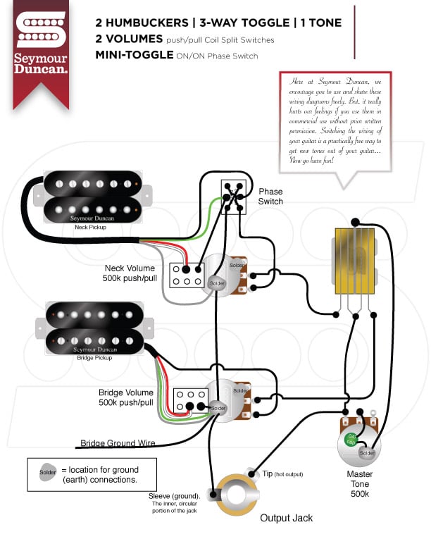
Seymour Duncan has most of what you want (diagram below) ...
https://www.seymourduncan.com/resources ... g-diagrams
Just take the single used sides of the two push-pull coil split switches shown and combine them into two sides of the DPDT switch on your diagram for your single coil split. If you're not using SD HBs, match for corresponding wire colours of manufacturer whose HBs you are using. Add whatever "tone cut" circuit/switch you have in mind, plus simple kill switch like this (except take output from your master tone, since you don't have master volume as shown there) ...
https://www.premierguitar.com/articles/ ... ill_Switch
Image
"I just knew I wanted to make a sound that was the complete opposite of a Les Paul, and that’s pretty much a Jaguar." Rowland S. Howard.

User avatar
zgw3kszo
PAT PEND
PAT PEND
Posts: 17
Joined: Mon Aug 31, 2020 8:04 pm

Re: Shadoweclipse13's Master Schematic Page!

Post by zgw3kszo » Mon Sep 28, 2020 8:39 am

This is quite messy but I've coloured and outlined everything to make it easier to follow, is it correct?

Image
I despise the Strat trem

User avatar
bodhi
PAT. # 2.972.923
PAT. # 2.972.923
Posts: 462
Joined: Mon May 20, 2019 12:47 pm

Re: Shadoweclipse13's Master Schematic Page!

Post by bodhi » Tue Sep 29, 2020 10:43 am

zgw3kszo wrote:
Mon Sep 28, 2020 8:39 am
This is quite messy but I've coloured and outlined everything to make it easier to follow, is it correct?

Image
Let's see, working backwards:
  • input/output at the jack: OK
  • kill switch: OK, strictly speaking not necessary to connect the other part to ground, but I don't believe it'll hurt
  • tone cut switch: that's probably not right, assuming you intended it to bypass the tone control completely?
  • tone pot: ok by itself, but the purple has no business being connected to the selector switch, that should go to a ground connection
  • pickup selector: remove the purple wire. Not sure about what the lugs are supposed to represent, you might need to use a multimeter to figure out what needs to be connected for the middle position to work, neck and bridge pickup separately probably works
  • bridge volume: maybe, don't know about which wire coding system is used by the pickups, and if that applies to the wire colors in the diagram. Might well be ok
  • neck volume: No, back of pot or one of the lugs needs to be connected to ground
  • phase switch: No, this does not need a connection to ground and should be reviewed
  • coil split switch: can't be bothered to try to figure this out based on pickup wire assumptions and other things going on
All in all, good work! These things are not simple to do and might take a surprising amount of time to figure out when they get a bit more complicated. However, with the above issues I believe that the whole system might not produce sound if wired up as planned.

The good thing is that you can easily work through this step by step, and there's no shame in that. Since you have four-wire humbuckers, I'd suggest wiring up one of them directly to the output jack first, and then add one thing at a time to the wiring, so you'll be able to pinpoint what's might be going on if something doesn't seem to work properly.

With that, remember that a phase switch doesn't do anything on its own, it'll only have an effect when both pickups are activated. A normal treble pot is connected in parallel (eg. it's own "dead end" fork to ground) with the hot signal. That also means that to have a "treble bypass" you just need to remove that connection (use the switch unhook the connection at "the fork"). A volume pot is in series (in line) with the main output, before (individuall volumes) or after (master volume) the pickup selector switch. A phase switch changes the hot and ground going into the pickup only, should not itself be connected to ground...
Jazzmaster project (got a body, placeholder neck, some pickups and ideas)
Tokai Telecaster Thinline with Creamery Pickups Filtertron and Tapped Tele
Blake Mills-inspired Strat project w/ Gold Foil and slide pickup

User avatar
Shadoweclipse13
PAT. # 2.972.923
PAT. # 2.972.923
Posts: 12446
Joined: Fri Feb 07, 2014 9:22 pm
Location: Stuck in the dimension of imagination

Re: Shadoweclipse13's Master Schematic Page!

Post by Shadoweclipse13 » Wed Sep 30, 2020 8:56 am

bodhi wrote:
Tue Sep 29, 2020 10:43 am
All in all, good work! These things are not simple to do and might take a surprising amount of time to figure out when they get a bit more complicated. However, with the above issues I believe that the whole system might not produce sound if wired up as planned.

The good thing is that you can easily work through this step by step, and there's no shame in that.
Completely agree! Some of this stuff isn't easy, and zgw3kszo started with a complicated wiring scheme! Piecing together bits from different schematics is how I got started in this stuff too, mostly for guitars for myself. Great job both of you guys!
Pickup Switching Mad Scientist
http://www.offsetguitars.com/forums/viewtopic.php?f=8&t=104282&p=1438384#p1438384

User avatar
Shadoweclipse13
PAT. # 2.972.923
PAT. # 2.972.923
Posts: 12446
Joined: Fri Feb 07, 2014 9:22 pm
Location: Stuck in the dimension of imagination

Re: Shadoweclipse13's Master Schematic Page!

Post by Shadoweclipse13 » Wed Sep 30, 2020 11:26 am

Added 2 schematics: standard Jag with a rhythm circuit that works with both pickups, and what I am calling my Ultimate JM (a 3-way Mustang slider in both the lead and rhythm circuits).
Pickup Switching Mad Scientist
http://www.offsetguitars.com/forums/viewtopic.php?f=8&t=104282&p=1438384#p1438384

User avatar
Embenny
PAT. # 2.972.923
PAT. # 2.972.923
Posts: 10363
Joined: Tue May 24, 2016 5:07 am

Re: Shadoweclipse13's Master Schematic Page!

Post by Embenny » Sat Oct 10, 2020 7:44 pm

This thread is awesome. Could I make a request?

I'm trying to figure out how to wire the rhythm volume pot and DPDT of a Jazzmaster as an on/off switch for a third pickup in series with whatever the lead circuit is doing (rhythm tone pot bypassed/unused).

Basically the inverse of a dial-a-tap. When the switch is off, I want the third pickup bypassed, and when it's on, I want a variable amount of series signal (to use like a preset boost).

I've found series blender schematics for middle pickups from strats mostly, but you have to turn the knob down to disengage it, which is slow and cumbersome mid-song with a roller pot. I'm hoping to just flick the switch to turn it off and go back to "stock" lead circuit tones. The strat diagrams note that you don't need a no-load pot like you do for a parallel blender, so it should work with the stock 1M pot, but integrating that with a DPDT is throwing me for a loop.

Any ideas?
The artist formerly known as mbene085.

User avatar
Shadoweclipse13
PAT. # 2.972.923
PAT. # 2.972.923
Posts: 12446
Joined: Fri Feb 07, 2014 9:22 pm
Location: Stuck in the dimension of imagination

Re: Shadoweclipse13's Master Schematic Page!

Post by Shadoweclipse13 » Sun Oct 11, 2020 11:12 pm

PM conversation now! Haha :D
Pickup Switching Mad Scientist
http://www.offsetguitars.com/forums/viewtopic.php?f=8&t=104282&p=1438384#p1438384

User avatar
spacelordmother
PAT. # 2.972.923
PAT. # 2.972.923
Posts: 57
Joined: Tue Aug 26, 2014 2:30 pm
Location: Western NY, USA

Re: Shadoweclipse13's Master Schematic Page!

Post by spacelordmother » Wed Oct 14, 2020 7:51 am

This thread is very very awesome. Should it be a sticky?
http://thewinterpalace.bandcamp.com
http://www.matthewgavette.com/noticing

User avatar
Shadoweclipse13
PAT. # 2.972.923
PAT. # 2.972.923
Posts: 12446
Joined: Fri Feb 07, 2014 9:22 pm
Location: Stuck in the dimension of imagination

Re: Shadoweclipse13's Master Schematic Page!

Post by Shadoweclipse13 » Tue Oct 20, 2020 12:14 am

mbene085 wrote:
Sat Oct 10, 2020 7:44 pm
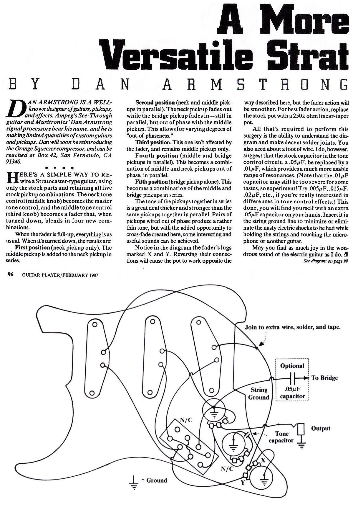
So, Mike and I have been talking through PM, and there's a mod he'd like to have, but I'm not positive how to achieve it. Basically, he wants a 3-pickup guitar where the bridge and neck pickups work with a 3-way (bridge, bridge + neck, neck) and the middle pickup is wired in series. My initial thought was to put the middle pickup in series using a toggle/slider switch like a strangle switch (one direction of switch = bypass, other direction of switch is a send to and return from the middle pickup) hooked into the output wire between the pickups selector and the volume and tone pots (or between the volume pot and the jack if that works better). The catch is that he also would like a blender pot to blend in varied amounts of the middle pickup, and I'm not sure how to add a blend pot that doesn't just act like a master volume. He sent me this, which I thought was really interesting:

Image
It looks like the blend pot (called the fader in the article) is wired to the pickup, but in parallel (kind of like how a tone pot is wired parallel to the pickup, i,e. the signal doesn't follow the ground shunt for the tone capacitors).

I was wondering if anyone could help with this one!
Pickup Switching Mad Scientist
http://www.offsetguitars.com/forums/viewtopic.php?f=8&t=104282&p=1438384#p1438384

Post Reply