 |
|
|
|
|
|
|
|
|
|
|
|
|
|
|
|
|
|
|
|
|
|
|
|
|
|
|
|
|
|
|
|
|
|
|
|
|
|
|
|
|
|
|
|
|
|
|
|
|
|
|
|
|
|
|
|
|
|
|
|
|
|
|
|
|
|
|
|
|
|
|
|
|
|
|
|
|
|
|
|
|
|
|
Buildup of a 1963 Fender
Jaguar
By Doug Lesho
12/2004
Revised
2/2006 |
|
|
|
DAY 2 |
|
|
|
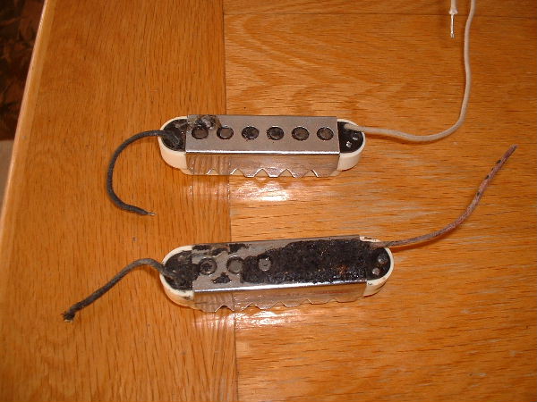
I
started this day out by cleaning the pickups, before heading out to the
hardware store. I selected this particular set based on their healthy
output, both are over 6.5k. I quickly abandoned my idea of leaving these
pickups connected to the shield, they were just too awkward to work with
that way. Anyone who has ever messed with an old Jag will probably imagine
what these pickups looked like.Typical, they had paint overspray all over
the claws and cover, the rotten gooey "spring" foam all over, and cut and
taped leads. I started on the neck pickup by carefully separating the
cover from the claw. The bobbins are usually tight in the cover, and this
pickup was no exception. I was tempted to wedge a small screwdriver
between them, but one must be very careful not to slip and gouge the
windings. I thought better of that idea and instead just wiggled the claw
and cover around patiently until they finally separated. The cover looked
awful. I used regular old toothpaste and a toothbrush to clean it up. (I
learned this trick on a previous Jag, but this time I did
not use my wife's toothbrush). That's my story and
I'm stickin' to it! |
|
|
|
 |
|
|
 |
|
|
|
|
|
Check out the shadow left by the claw due to 41
years of natural aging. |
|
|
|
|
|
|
After pulling the cloth lead up through the hole,
I heated up the solder connection from the bottom side and pulled the lead
through. Next, I threaded the new lead through the hole, leaving much
slack before making the turn back down to the connection. I again heated
the joint and poked the conductor through. After a brief cooling period, I
pulled the slack back down through the first hole.This is very easy to do,
and I can't believe how many people just splice and tape the pickup leads
instead of effecting a proper repair! After applying a coat of
automotive wax to the claw, I reassembled the pickup. Holding my breath, I
checked it with the meter. It read a healthy 6.88k. I then performed
the duplicate procedure on the bridge pickup. It read 6.87k, these pickups
are almost matched identically. |
|
|
 |
|
|
|
|
 |
|
|
|
|
|
|
|
|
Comparison shots of a dirty and clean pickup. The
difference was much more dramatic in person! |
|
|
|
|
|
 |
|
|
|
|
|
|
 |
|
|
|
|
|
Now I was off to the store. I bought 2 new
soldering iron tips, a small sheet of .032 aluminum, a sponge, and a new
roll of solder. |
|
|
|
 |
|
|
 |
|
|
|
|
 |
|
|
|
|
|
|
|
|
The sheet was way more than I needed for the few
glazier points I needed to fabricate, however this was the smallest sheet
I could find. It was only a couple bucks and will probably come in handy
for something down the road. A pair of tin snips and voila! I had more
glaziers than I could ever hope for. |
|
|
|
|
|
|
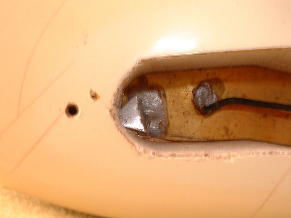
A glazier point installed in the cavity, securing
the brass shield as intended. Note the finish checking and the "nail
hole". |
|
|
|
|
|
I
installed the glaziers in their original location(s) using the same ball
peen and drift that came in handy yesterday. Once you find the spot, they
go in very easily with minimal tapping. I like to drive them in just a bit
further than they originally were, to ensure they are tight. Once in
place, a blob of solder ensures they stay put. The solder attaches to the
brass and pools over and around the glazier, which is driven into the
body. The last thing you want is a glazier rattling around inside your
guitar. |
|
|
|
It's a good idea to tape off the rim of each
cavity with masking tape. This helps to avoid burns and/or chips to the
finish. No matter how many times I tell myself I'm going to be careful, I
always end up touching the sides with the iron sooner or later. Masking
tape is good and cheap insurance. |
|
|
 |
|
|
|
|
|
|
 |
|
|
|
|
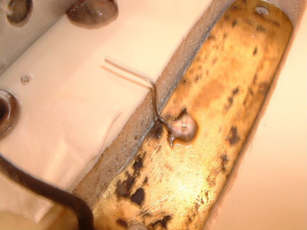
You can use the spot of solder that secures a
glazier to also connect the ground wires. Leo sometimes did it this way,
who are we to argue? Note the masking tape on the cavity
edges. |
|
|
|
|
|
 |
|
|
|
|
|
|
The pickup cavity shielding will be secured with
the pickup screws, therefore it does not need any glaziers. All of the
shielding gets connected together by the black ground wires, through the
cavity wiring holes. This will ensure a good shield and minimal hum.
Speaking of grounding, I almost forgot about the mysterious little
unshielded wire that many Jaguars have coming up from the bridge pickup
cavity. Not always present, it's designed to ground the pickguard
shield. One end is connected to the brass shield, and the aluminum
pickguard shield just sits on top of it once installed. I didn't
have one, so I had to make one. |
|
|
|
|
|
 |
|
|
|
 |
|
|
The ground wires with the terminal ends are used
to ground the chrome control plates. They attach to one of the slide
switch screws. |
|
|
|
|
|
|
|
Now it's time to start the actual circuit wiring.
I began by applying the new spring foam that I got from Bass Parts
Resource. They are listed as a Jazz Bass part, but work perfectly. They
are self-adhesive foam blocks that fit perfectly between the pickup mount
holes without any alteration. I set out my control plates, switches and
pots and got a cool damp sponge ready. Dabbing the soldering tip on the
sponge between connections will help keep it clean. Clean means hot.
There's nothing more frustrating than placing the tip on a lug and having
to wait a couple of hours for the solder to melt. |
|
|
|
|
|
|
|
|
|
|
I made this little guy from one leg of an unused
capacitor that was laying about. Here it is installed (right). This often
missing gem will complete the shielding circuit. Check your Jaguar to see
if you have one, they really do make a difference! |
|
|
|
|
|
 |
|
|
|
 |
|
|
|
|
|
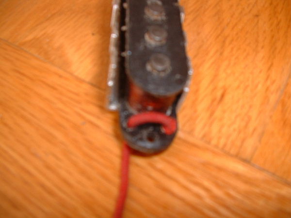
After routing the red lead from the bridge pickup
into the 3-switch cavity, I mounted the pickup. At this point, I also
started to mount the neck pickup. As the screws were about halfway down, I
remembered that the plethora of wires from the rhythm circuit had to run
through the neck pickup cavity. So I removed the neck pickup and turned my
attention to the roller plate and made the appropriate connections. Then I
pulled the wires through into the neck pickup cavity and into their
respective locations. |
|
|
|
 |
|
|
|
 |
|
|
|
|
These original pickup mounting screws are very
difficult to find. Luckily, I had two complete sets of four to choose
from. |
|
|
|
|
|
 |
|
|
|
|
|
|
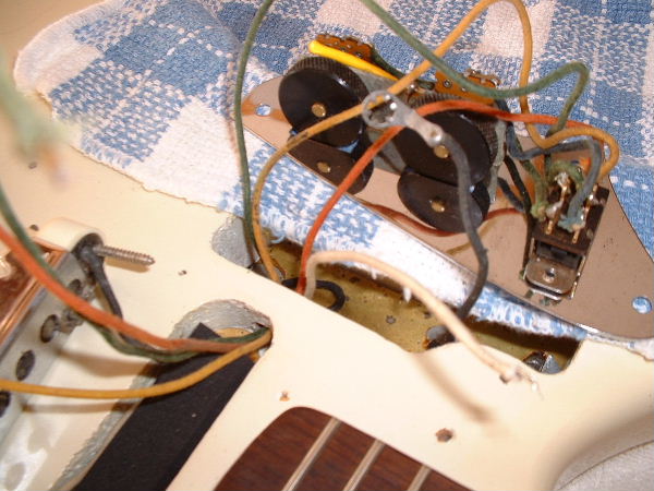
The pretty little colored wires are
all routed nicely and neatly to their final
destinations. |
|
|
|
|
|
 |
|
|
|
 |
|
|
|
|
|
The main circuit pots and jack are prone to
loosening. I ensured that the star washers were on the shaft under the
plate and secured tightly with a 1/2" socket. |
|
|
|
|
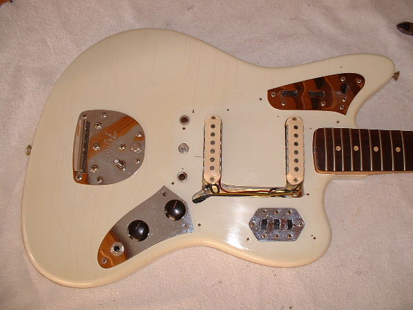
The rhythm circuit control plate
and pickups are installed. |
|
|
|
|
|
|
I
followed in suit connecting the main circuit and the 3-switch panel. After
all the connections were made, I installed the plates and the main control
knobs. |
|
|
|
 |
|
 |
|
|
|
|
|
The pots are an original matched set from the 37th
week of 1963. The other leg from the cannibalized capacitor from above
made a nice bridge between them, just as original. |
|
|
|
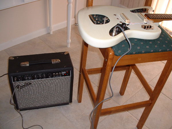
With anticipation, I then dragged out my trusty
little solid-state Champion 110. It's a good little amp to use for
testing, there are very few variables.To test if the circuits are correct,
I performed a "tap test" on the pickups using a small flat screwdriver.
First, I configured the switches for the main circuit, bridge pickup only.
With a gentle tap on the pickup poles, it sure enough transferred
|
|
|
|
|
 |
|
|
|
|
 |
|
|
|
|
|
|
|
|
 |
|
|
|
|
|
|
|
through to the amp. Next I tried the neck pickup.
Again, it worked like a champ (pun intended!). Next I tried both pickups
on, to a favorable reaction. Finally, I switched it over to the rhythm
circuit and verified that only the neck pickup was working. I rotated the
volume pots on and off for both circuits and verified they were working.
Everything was perfect! And what's more, this Jag was relatively
quiet, no snap, crackle or pop. I am very pleased!
Knowing
that I had this typing to do, I went ahead and cleaned up for the day.
Tomorrow I will file and fit the shrunken pickguard, clean the bridge and
saddles, and do the final assembly, set-up, and polishing. I can hardly
wait! |
|
|
|
|
|
|
OffsetGuitars.com Forums
/ Day One / Day Two / Day Three |
|