Hi
I’m sure this has been gone over a million times but I’m looking for a wiring diagram for a Jazzmaster with a 4-way tele switch and the rhythm circuit still included.
I am a total novice with wiring. I can use a soldering iron and can follow instructions but I’m not sure I can figure this out on my own.
My stock 3-way switch is shot and if I’m taking it out I would like to just put in the 4-way while I’m at it
Any help would be appreciated
Thanks!
Need help with 4-way Jazzmaster mod
-
timtam

- PAT. # 2.972.923

- Posts: 2906
- Joined: Sun Oct 22, 2017 2:42 am
- Location: Melbourne
Re: Need help with 4-way Jazzmaster mod
So by 4-way you mean with series as the 4th position ? I am not aware of an existing wiring diagram for a JM with a 4-way on the lead circuit and also having the conventional rhythm circuit.
Series requires that you can switch the coil ground wire on one pickup - grounded as normal when not in series, and connected to the other pickup's hot when in series. At least with jazzmaster pickups that doesn't require any pickup surgery - with no metal in the JM pickup casing, there is no ground wire for that metal shared with the coil -ve ... and thus no need to separate that into two wires (as there is with jag pickups, for example for the Marr jag's series function).
The only JM with a 4-way is the CME/FSR Player JM released a few years back. Its circuit should be as shown in this schematic (no official wiring diagram has been released). You can see how the neck pickup's coil -ve/ground wire is switched to connect to the bridge's positive in the series position 4.

The CME/FSR Player JM does not have the rhythm circuit (although routed for one), nor do the jags with 4-ways ... the Marr jag and Am Pro I jag.
To combine a 4-way (lead) circuit like that above with the conventional rhythm circuit, you would have to prevent the 4-way from being able to do the series connection of neck coil -ve to bridge +ve (hot) when the rhythm circuit is selected. The rhythm circuit wouldn't work correctly with that connection possible. But the conventional rhythm circuit switching only operates on the neck hot; neck coil -ve is assumed to always be connected to ground in the conventional JM circuit (see schematic below).
Off the top of my head, one way of avoiding that problem would be to do the 4-way's ground wire switching on the bridge pickup instead of the neck pickup - literally just cross out 'neck' on the above diagram's neck pickup and write 'bridge'; and vice-versa for the bridge pickup. That would also make the neck into position 1 on the 4-way, and the bridge into position 3 (you can just physically rotate the 4-way switch in the cavity if you want to restore the regular physical positions 1 and 3).
BTW you may have to enlarge the JM's toggle switch cavity a little to accommodate the 4-way.
Below is the conventional JM schematic, showing the rhythm circuit switching. You would paste the rhythm circuit from there onto the above diagram (taking the hot from the neck pickup to the RC as shown below - which gets sent into the rhythm circuit when selected, or sent to the 4-way in the lead circuit position).

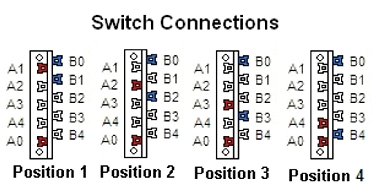
The 4-way switch layout is ....
Series requires that you can switch the coil ground wire on one pickup - grounded as normal when not in series, and connected to the other pickup's hot when in series. At least with jazzmaster pickups that doesn't require any pickup surgery - with no metal in the JM pickup casing, there is no ground wire for that metal shared with the coil -ve ... and thus no need to separate that into two wires (as there is with jag pickups, for example for the Marr jag's series function).
The only JM with a 4-way is the CME/FSR Player JM released a few years back. Its circuit should be as shown in this schematic (no official wiring diagram has been released). You can see how the neck pickup's coil -ve/ground wire is switched to connect to the bridge's positive in the series position 4.
The CME/FSR Player JM does not have the rhythm circuit (although routed for one), nor do the jags with 4-ways ... the Marr jag and Am Pro I jag.
To combine a 4-way (lead) circuit like that above with the conventional rhythm circuit, you would have to prevent the 4-way from being able to do the series connection of neck coil -ve to bridge +ve (hot) when the rhythm circuit is selected. The rhythm circuit wouldn't work correctly with that connection possible. But the conventional rhythm circuit switching only operates on the neck hot; neck coil -ve is assumed to always be connected to ground in the conventional JM circuit (see schematic below).
Off the top of my head, one way of avoiding that problem would be to do the 4-way's ground wire switching on the bridge pickup instead of the neck pickup - literally just cross out 'neck' on the above diagram's neck pickup and write 'bridge'; and vice-versa for the bridge pickup. That would also make the neck into position 1 on the 4-way, and the bridge into position 3 (you can just physically rotate the 4-way switch in the cavity if you want to restore the regular physical positions 1 and 3).
BTW you may have to enlarge the JM's toggle switch cavity a little to accommodate the 4-way.
Below is the conventional JM schematic, showing the rhythm circuit switching. You would paste the rhythm circuit from there onto the above diagram (taking the hot from the neck pickup to the RC as shown below - which gets sent into the rhythm circuit when selected, or sent to the 4-way in the lead circuit position).
The 4-way switch layout is ....
"I just knew I wanted to make a sound that was the complete opposite of a Les Paul, and that’s pretty much a Jaguar." Rowland S. Howard.
-
Joshl-m

- PAT PEND

- Posts: 4
- Joined: Sun Apr 20, 2025 4:11 pm
Re: Need help with 4-way Jazzmaster mod
Thank you! I’m going to have to take some time to digest that. I’m willing to go without the rhythm circuit maybe temporarily while I figure it out but I am one of the people who really likes having it
-
bodhi

- PAT. # 2.972.923
- Posts: 597
- Joined: Mon May 20, 2019 12:47 pm
Re: Need help with 4-way Jazzmaster mod
Yeah, as above it often might make sense to have the bridge pickup be the one with the permanent ground. There are also other Switchcraft slide switches that have more lugs that should fit in the rhythm cavity if required (probably not in this case), though it might be a bit routing-dependent. I'm mostly working on my own builds, so I'm not a 100% sure if f.e. the standard route always works or not...
Jazzmaster project (got a body, placeholder neck, some pickups and ideas)
Tokai Telecaster Thinline with Creamery Pickups Filtertron and Tapped Tele
Blake Mills-inspired Strat project w/ Gold Foil and slide pickup
Tokai Telecaster Thinline with Creamery Pickups Filtertron and Tapped Tele
Blake Mills-inspired Strat project w/ Gold Foil and slide pickup
-
taherbert
- PAT PEND
- Posts: 11
- Joined: Sun Mar 27, 2022 11:36 am
Re: Need help with 4-way Jazzmaster mod
I am waiting on a pickguard from Spitfire right now to build almost the exact same thing (except I'm going to do a passive bass and treble roll off instead of a classic rhythm circuit). There is no schematic on the internet, I've had to piece it together from a number of different variations. The 4-way tele switching for series parallel is pretty straightforward:

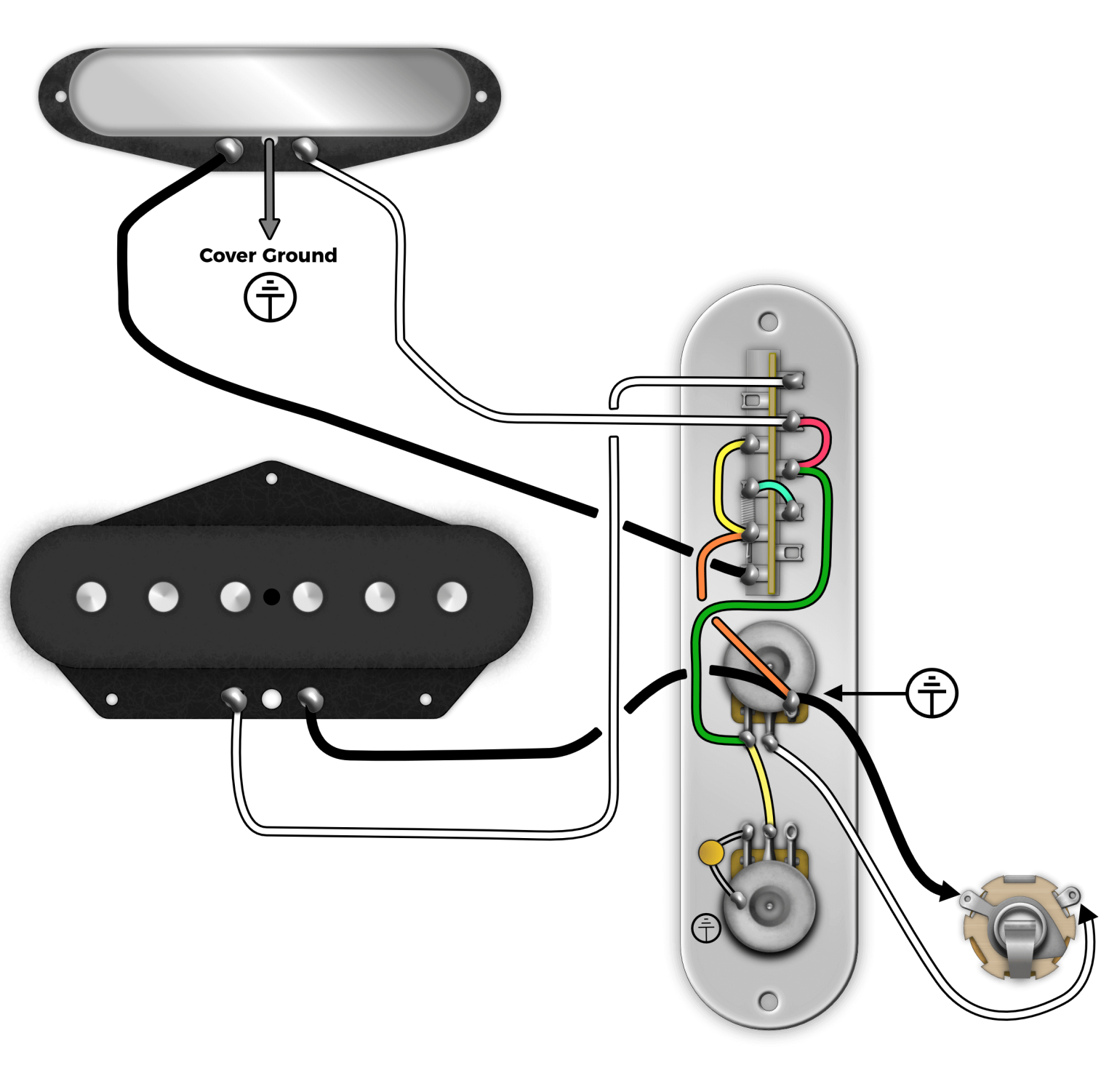
And Timtam is correct, the tricky part of this is where to put the ground for the second pickup. Additionally, I am using Wide range humbuckers with traditional shiled wiring, so I have to make sure that pickup case and wire is insulated from the cavity shielding at all points.
The easiest way to do this with a 4-way switch would be pickups --> 4way switch as shown above --> rhythm switch as wired below, but rather than the 3-way switch, use the green wire from the Fralin tele diagram above:

Now you have a rhythm circuit that can use all pickup combinations and you can put whatever Vol-Tone stack you want in there.
And Timtam is correct, the tricky part of this is where to put the ground for the second pickup. Additionally, I am using Wide range humbuckers with traditional shiled wiring, so I have to make sure that pickup case and wire is insulated from the cavity shielding at all points.
The easiest way to do this with a 4-way switch would be pickups --> 4way switch as shown above --> rhythm switch as wired below, but rather than the 3-way switch, use the green wire from the Fralin tele diagram above:
Now you have a rhythm circuit that can use all pickup combinations and you can put whatever Vol-Tone stack you want in there.
-
Joshl-m
- PAT PEND
- Posts: 4
- Joined: Sun Apr 20, 2025 4:11 pm
Re: Need help with 4-way Jazzmaster mod
If I used a 3pdt switch, would that be another possibility to use the 4 way switch and keep the rhythm circuit on all positions?
-
taherbert
- PAT PEND
- Posts: 11
- Joined: Sun Mar 27, 2022 11:36 am
Re: Need help with 4-way Jazzmaster mod
Yes, if you wire the output of the 4-way switch to the middle lug of the Rhythm switch like in the last picture (green wire from the second picture), the 4-way switch will send the output of whatever pickup combo you choose to that switch. If wired as in the 3rd picture, the rhythm 3pdt switch routes the output of the pickup selector to one of two parallel Vol-Tone circuits (Lead or RC). That's how I have wired all my Jazzmasters, but that's not how the original schematic does it.
In the traditional Rhythm circuit, only the neck pickup works with the RC because the neck pickup output is directly wired to that 3pdt switch, and the switch decides whether to route it through the 3-way toggle or the RC. I don't know why Leo designed it that way, perhaps because the wire runs are shorter and less RF or it was just cheaper and used less wire? I haven't had any real noise issues more than just a standard single coil noise, but I've also used shielding paint on all my JM body cavities.
In the traditional Rhythm circuit, only the neck pickup works with the RC because the neck pickup output is directly wired to that 3pdt switch, and the switch decides whether to route it through the 3-way toggle or the RC. I don't know why Leo designed it that way, perhaps because the wire runs are shorter and less RF or it was just cheaper and used less wire? I haven't had any real noise issues more than just a standard single coil noise, but I've also used shielding paint on all my JM body cavities.
-
Joshl-m
- PAT PEND
- Posts: 4
- Joined: Sun Apr 20, 2025 4:11 pm
Re: Need help with 4-way Jazzmaster mod
Thanks! This all helps a lot. I have also just printed a bunch of diagrams out so I can get a really clear visual of what is happening and what my options are. It’s a lot better than flipping back and forth on my phone.
I will report back once I have given it a shot. It will likely be a week or two before I have a chance to take a crack at it.
I will report back once I have given it a shot. It will likely be a week or two before I have a chance to take a crack at it.